
DISASSEMBLY AND ASSEMBLY
| Paragraph | |
| General |
13 |
| Removal of groups |
14 |
| Replacement of groups |
15 |
| Magazine, disassembly |
16 |
| Magazine, assembly |
17 |
| Front band, disassembly |
18 |
| Front band, assembly |
19 |
| Barrel and receiver group, disassembly |
20 |
| Barrel and receiver group, assembly |
21 |
| Trigger housing Group, disassembly |
22 |
| Trigger housing Group, assembly |
23 |
| Operating slide group, disassembly |
24 |
| Operating slide group, assembly |
25 |
| Bolt group, disassembly |
26 |
| Bolt group, assembly |
27 |
| Stock group, disassembly |
28 |
| Stock group, assembly |
29 |
13. GENERAL. -- a. Disassembly and assembly is
treated herein under two general heads: removal and replacement of groups to the
extent required for cleaning, adjustment and minor repairs, and detailed
disassembly and assembly of the component parts of each group.
b. When disassembling, attention should be paid to
the position and manner of removal of groups and parts as an aid to assembly. A
group is a number of parts which either function together or are intimately
related to each other and should, therefore, be considered together.
c. Disassembled groups and parts should be placed
upon a clean, flat surface and care observed to guard against loss of pins,
springs and other small parts. All parts should be thoroughly cleaned and oiled
before assembly, and the carbine lubricated and hand operated, when assembly is
complete, to test mechanisms.
d. The groups may be
removed and disassembly accomplished with the tools provided and listed in SNL
B-28.
e. Disassembly, assembly, and such repairs as
may be handled by using arms personnel will be undertaken only under the
supervision of an officer or the chief mechanic.
f.
Disassembly of the following groups and parts are generally prohibited to the
using arms:
(1) Magazine assembly.
(2) Barrel and receiver assembly.
(3) Barrel with gas cylinder assembly.
(4) Rear sight base.
(5) Front sight.
(6) Front band assembly.
(7) Recoil
plate.
(8) Operating slide assembly.
(9) Stock and hand guard assemblies.
14. REMOVAL OF GROUPS. -- a. Barrel and receiver
group. -- (1) Release magazine from receiver by pressing the magazine catch to
left and withdrawing magazine downward, if it does not fall out.
(2) Retract bolt and glance into chamber to insure
that carbine is unloaded.
(3) Press sling swivel
back against stock. Loosen front band by unscrewing front band screw part way
(figure
6). (The screw may be loosened with the head of a carbine cartridge). Press
forward end of locking spring towards stock (figure 6) and
slide front band forward over front band locking spring. The front band cannot
be removed from barrel until front sight is removed.
(4) Remove hand guard by sliding it forward on
barrel until the liner is disengaged from undercut in the forward face of
receiver, and then lifting it from barrel.
(5) Lift
forward end of barrel and receiver group from stock (about 15 degrees) until lug
at rear end of receiver is disengaged from under retaining notch in face of
recoil plate (Figure 7).
When lug is clear, pull barrel and receiver forward and up and lift out of stock
with trigger housing group attached.
b. Trigger
housing group. -- Push out trigger housing retaining pin from left side of
forward end of trigger guard until clear of lug on receiver. Pull trigger
housing forward until rear lug is clear of mating grooves in receiver, and then
remove trigger housing group from receiver. Press retaining pin home in trigger
housing to prevent loss. (See Figure 8,
showing groups removed.)
c. Operating slide group
(Figures 9
and 10).
-- (1)Draw operating slide spring guide sslightly to rear until it is disengaged
from operating slide, and then pull to right, and forward, and withdraw guide
and spring from well in receiver. Disengagement of guide may be facilitated by
retracting slide part way, then, holding spring and guide, push slide forward
and remove slide as above.
(2) Draw operating slide
slowly to rear until forward face of stop is in line with forward face of top of
receiver. Pull handle up and to right until guide lug is free of retaining
groove in receiver. Push body of slide forward until rear face of stop is in
line with forward face of top receiver. Pull handle up and to right until guide
lug is free of retaining groove in receiver. Push body of slide forward until
rear face of stop is in line with forward face of top of receiver and rotate
slide body counterclockwise, freeing lug (by means of relief cut) from retaining
guideways in barrel. Remove slide from barrel.
d.
Bolt (Figures 11 and 12) -- Grasp
bolt by cam lug and slide to rear until face of bolt is behind locking shoulder
in receiver. Rotate bolt counterclockwise, lift up to angle of about 45 degrees,
and turn bottom up. Pull bolt forward and up, out of receiver. Bolt may be
removed with trigger housing in position, but hammer must be in cocked position.
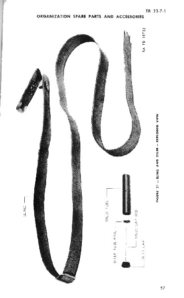
e. Sling. -- To remove sling, unbutton rear end of sling, withdraw from around oiler, and pull oiler to right out of aperature in stock. Unlock sling buckle and pull sling out of buckle and then out of sling swivel. Replace oiler in its loop in sling and rebutton sling, to prevent loss of parts.
15. REPLACEMENT OF GROUPS. -- a. Bolt. -- With
hammer cocked (trigger group assembled), grasp receiver in left hand and bolt in
right, top down. Insert rear of bolt, at about 45 degree angle, into rear top of
receiver, and then turn bolt top up, and cam lug facing up, at an angle of about
45 degrees. Fit left guide lug of bolt in its groove in left side of receiver
and then rotate bolt clockwise and slide forward. Bolt may be replaced with
trigger housing in position, but hammer must be in cocked position.
b. Operating slide group. -- (1) With Hammer Cocked
(trigger housing group assembled), hold body (forward end) of operating slide in
the left hand and receiver in right. Place slide body against under side of
barrel so that lug on right side is seated in its guideway, and lug on left side
is opposite (mating with) relief cut in guideway in left side of barrel.
Position bolt so that cam lug is in position to enter camming aperature in left
side of slide handle. Start bolt cam lug into camming aperature in slide handle,
and then rotate body of slide around barrel clockwise, until bolt lug fully
enters camming aperature in slide handle and slide body lug enters relief cut in
barrel. When lugs are so mated, push slide to rear until forward face of
operating slide stop is level with forward face of rear top of receiver, and
press operating slide handle in towards receiver so that lug on handle mates
with relief cut in guideway on right side of receiver. Reciprocate slide to
assure proper mating at both ends, and with bolt.
(2) Place operating slide spring guide in spring and free end of spring in well
in forward face of receiver. compress guide against spring and, with slide fully
forward, insert nose of guide head into indentation in right rear face of slide
body. Operate slide a few times to test assembly. Positioning of guide head may
be facilitated by inserting rear end of spring and guide in well in receiver
then engage forward end of spring and rear face of operating slide and retract
slide part way, compressing spring. Hold guide and spring in retracted position
and move operating slide forward, then seat guide head as above.
c. Trigger housing group. -- With bolt in forward
position and hammer cocked, place flat side of trigger housing flat upon under
side of receiver with forward U-lug just ahead of lug on forward end of
receiver. Slide housing to rear so that rear T-lug mates with and slides between
L-lugs on rear of receiver, and U-lug on forward end of trigger housing mates
with lug on forward end of receiver. Align pin holes in both forward lugs and
insert trigger housing retaining pin from right side so that it is flush with
both sides of U-lug. Be sure that trigger housing retaining pin spring is
positioned in pin when inserting pin. Start pin (if fully withdrawn) into
hole at slight angle so as to cam the spring into the hole.
d. Barrel and receiver group. -- (1) Grasp stock in
right hand and barrel and receiver group in left hand (by barrel). Insert
trigger housing in aperature in top of stock and push back and down, with barrel
at an angle of about 15 degrees, until retaining lug on rear of receiver is
beneath lip of retaining aperature in face of recoil plate, and back against
rear face of recoil plate. Then slowly depress muzzle of barrel, at same time
pressing to rear. If retaining lug does not cam up into aperature in recoil
plate easily, do not force, but raise muzzle again and repeat operation until
lug cams easily into aperature. Retaining aperature in recoil plate is an
undercut, and retaining lug on rear of receiver has to cam into it after nose of
lug is behind undercut. If pressure is exerted before this is accomplished, the
great leverage obtained will injure the parts.
(2)
When mating between lug and aperature is accomplished, lower barrel into bed in
stock. Place hand guard flat on barrel and slide to rear so that metal liner
mates with and enters retaining groove in forward face of receiver. Press hand
guard fully home and slide front band over forward end of stock and hand guard,
and press back, until behind front band locking spring. Seat evenly and tighten
front band screw.
e. Sling. -- Thread free (button)
end of sling through sling swivel from the rear side and then through (unlocked)
locking buckle. Place oiler in aperature in stock from right side, then thread
button end of sling around oiler from rear to front. Mate button holes and
insert button. To adjust sling, unlock buckle, pull sling through to desired
length and relock buckle. (See Figure 21,
showing early type of sling. This sling has a friction type adjusting buckle and
snap instead of button).
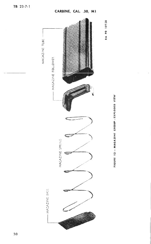
16. MAGAZINE, DISASSEMBLY. (Figure 13).
-- Grasp magazine in left hand with base up and rounded face towards the body.
With left thumb press up on forward (rounded) end of magazine base until the
base can be slid to rear out of its retaining grooves in base of tube. Movement
can be started by inserting rim of cartridge or similar instrument in recess in
top of base. Remove magazine spring through opening thus obtained. Follower
should not be removed unless necessary as tube may be sprung in process. To
remove: position follower at bottom of tube. Insert screw driver or similar tool
from top of tube to bear on rear end of follower and press on follower until
stop flange is clear of tube. If flange will not rotate out, press down on
opposite end to assist rotation. Do not force. Grasp flange and rotate follower
out of tube.
NOTE: Magazine
should not be disassembled except in emergency or for salvage.
17. MAGAZINE, ASSEMBLY. -- Insert short (curved) end of follower into rear bottom (flat) side of magazine tube. Press down and rotate, until end of long side snaps under retaining flange. If necessary insert screw driver or similar tool into top of tube to hold short end, and assist in rotation. Do not force unduly or magazine will be distorted. Push follower to top of tube and insert magazine spring with long side to the rear. (This permits the follower to slide easier in the tube.) Compress spring with thumb, and slide square end of base into retaining grooves in bottom of magazine until retained by projection on curved end, slipping inside tube. Push follower down in tube and release to test smoothness of functioning. If follower does not slide up smoothly by spring action, tube has been distorted and should be corrected.
18. FRONT BAND, DISASSEMBLY. -- Unscrew front band screw, remove it from band and remove swivel. There is no further disassembly of the band as the clip and piece are spot welded together. The front band cannot be removed from the barrel until the front sight is removed.
19. FRONT BAND, DISASSEMBLY. -- Place front band swivel between ends of front band piece with flat side facing forward and away from front band clip. Inset screw from top through piece and swivel and screw in part way. Do not tighten until band is assembled to stock and hand guard. If front band has been removed from barrel it should be replaced so that the piece is towards the muzzle.
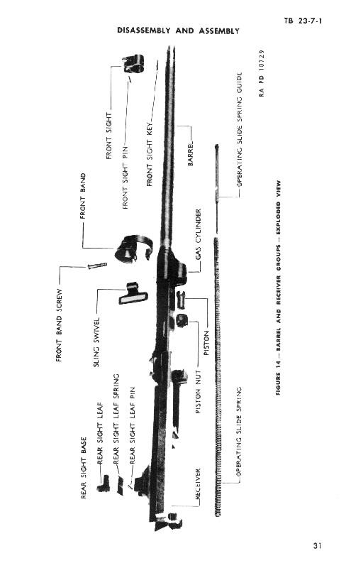
20. BARREL AND RECIEVER GROUP, DISASSEMBLY (Figure 14).
-- a. Removing barrel from receiver. -- TThe barrel should not be removed from
the receiver except for replacement. To remove, completely disassemble barrel
and receiver. Wedge a hard wood block in receiver to prevent spring of the sides
and clamp receiver in a vise having leather covered jaws. Position receiver in
vise as near to end as possible and clamp only tight enough to hold securely.
Place strap wrench on barrel near receiver end and unscrew barrel
anti-clockwise. (Barrel has right hand thread).
b.
Front sight. -- Do not remove unless necessary, as both ends of front sight
blade pin are crimped into the body of the front sight blade and the front sight
key is staked at the rear end into its keyway in the barrel. To remove sight
from barrel, punch out front sight pin and drive sight forward from barrel,
using hard wood block or brass drift. To remove key from barrel, tap lightly to
rear to loosen staking, using hard wood block or brass drift, and lift key out
of keyway.
c. Gas cylinder group. -- (1) Integral
type. -- Unscrew piston nut from gas cylinder. Remove nut, elevate muzzle of
barrel and slide piston out of gas cylinder. If piston will not slide out, tap
cylinder lightly with wood block. The integral type gas cylinder permits of no
further disassembly.
(2) Removable type. -- Do not remove unless
necessary for replacement. Before removing disassemble barrel and receiver
and remove front sight group as described in subparagraph b above. To remove gas
cylinder: remove piston nut and piston as in (1) above, punch out retaining pin,
and drive gas cylinder forward off barrel, using hard wood block or brass drift.
When driving off, make contact with rear face of cylinder near barrel, so as to
exert driving force as near parallel to barrel as possible.
d. Rear sight. -- To disassemble rear sight group;
spot a mark on rear sight base and receiver for proper alignment upon assembly,
drive out rear sight leaf pin and lift leaf and spring from sight base. Drive
out base from right to left, using block of hard wood or brass drift (dovetail
tapers to right).
21. BARREL AND RECEIVER GROUP, ASSEMBLY. -- a.
Replacing barrel in receiver. -- To assemble barrel to reciever, clamp reciever
in vise as described in paragraph 20 above. Start threading by hand and then use
strap wrench to screw barrel tightly into reciever. Screw barrel into reciever
(clockwise) tightly and turn until qualification marks on bottom of barrel and
reciever are in line. Be careful to start threading correctly. When assembled,
flat lower surfaces of barrel and reciever should be parallel, and extractor
aperature in rear face of barrel should mate with extractor when bolt is locked.
b. Gas cylinder. -- (1) Integral type. -- Inspect
gas cylinder and port for foreign matter and wipe clean. Insert piston in gas
cylinder, head first, and screw piston nut in snugly allowing rear of piston to
protrude through nut. Shake barrel to be sure piston moves freely in gas
cylinderand protrudes sufficiently through nut (approx. ¼ inch).
(2) Removable type. -- (a) The gas cylinder must be
assembled to the barrel before front sight is assembled. Slide gas cylinder on
barrel with piston aperature on under side of barrel and facing to the rear.
Aline flat sides of gas cylinder as closely as possible with flat sides of rear
of barrel and drive cylinder on barrel, using block of hard wood or brass drift,
until pin holes in cylinder and pin groove in barrel aline. Insert gas cylinder
pin and drive flush with both sides of cylinder.
(b) Assemble piston to gas cylinder as described in subparagraph b (1) above.
NOTE: Gas cylinder is
aligned and drilled for pin, and gas port then drilled upon manufacture. In
assembling new gas cylinder to old barrel, the alignment of the gas port should
be checked.
c. Front sight.-- Place front sight key
in keyway in top of barrel muzzlewith pin cut facing up. Tap key snugly to
forward end of keyway, and stake rear end of keyway to hold key in position.
Slide front sight onto barrel with sloping faces of wings facing to rear. Mate
keyway with key in barrel, and drive sight on barrel until pin hole in sight is
in alignment with pin-cut in key. Insert pin and drive through until not quite
flush with either side of sight. Stake metal over both ends of pin to hold in
position.
d. Rear sight group. -- (1) If rear sight
base has been removed, drive base into dovetail aperature in rear top of
reciever from the left side (dovetail tapers to the right) until aligning marks
have been made, aline rear sight base so that center line of bore (chamber) and
front sight blade aline midway between wings of rear sight base.
(2) Position leaf spring between wings of base and
press down leaf upon spring until pin holes in base and leaf aline. Insert rear
sight leaf pin and drive flush. When leaf is in position, recessed face of
aperature should face to front.
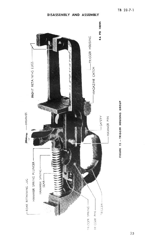
22. TRIGGER HOUSING GROUP, DISASSEMBLY (Figure 15).
-- a. Hammer group. -- (1) If hammer is nnot in forward position, pull trigger
and ease hammer forward with thumb.
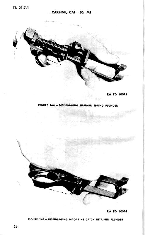
(2) Insert
small punch or similar tool into hole in hammer spring guide and pull back until
guide is clear of notch in hammer (Figure 16);
then swing guide to right to clear hammer, and ease forward against force of
spring until guide is clear of well in trigger housing. Pull guide from hammer
spring. Punch out hammer pin and remove hammer.
b.
Trigger and sear group. -- Pry trigger spring until clear of seating slot in
rear of trigger; then pull forward and up and remove from aperature in trigger
housing. (Trigger spring may also be removed from the rear). Hold sear with
thumb, against force of spring, and punch out trigger pin. Invert trigger
housing and shake trigger and sear group from top of trigger housing. Pull sear
spring from well in trigger.
c. Magazine catch
group. -- Hold trigger housing bottom up in left hand, and with right hand
insert small punch or similar tool into hole in lower face of trigger housing
just forward of the bow (Figure 16).
Engage punch ahead of magazine catch retainerplunger and pry plunger back from
engagement with magazine catch. (Hold magazine catch with left thumb so that
magazine catch spring and plunger do not fly out). Remove magazine catch and
pull magazine catch plunger and spring out of trigger housing.
d. Safety group. -- Safety cannot be removed from
trigger housing until magazine catch has been removed from trigger housing,
safety spring and plunger and magazine catch retainer plunger may be removed
through forward face of trigger housing, and safety pushed out of
aperature. (Magazine catch retainer plunger and safety spring plunger are
positioned on opposite ends of the safety spring).
23. TRIGGER HOUSING GROUP, ASSEMBLY (Figure 17).
-- a. Safety group. -- (1) Inset safety into its aperature ahead of trigger bow,
with trigger cut facing to rear.
(2) Assemble
safety spring plunger and magazine catch retainer plunger to safety spring.
Insert assembly into well in forward face of trigger housing (in magazine catch
slideway). Operate safety sufficiently to see that safety spring plunger is
engaged in aperature in forward face of safety.
b.
Magazine catch group. -- (1) Place magazine catch spring plunger in spring in
well in right side of trigger guard housing (just ahead of safety) with plunger
facing out.
(2) Insert magazine catch into its
guideway in forward face of trigger housing, from right side, with flange facing
to rear, and press to left until stopped by retainer plunger. Depress retainer
plunger into well in trigger housing and push catch to left until retaining
plunger clicks into position to retain catch in guideway. Operate safety
and catch a few times to test mechanism.
c. Trigger
and sear group. -- (1) Place trigger in trigger housing with long arm forward,
and insert trigger pin part way to hold in position. Insert sear spring in well
in body of trigger.
(2) Place sear in position in
top of trigger, with long point facing and free end of sear spring seated in
aperature in rear face of sear. Press sear back and down against force of spring
until holes in trigger housing, trigger and sear are in line and then push
trigger pin all the way trhough until flush with both sides of trigger housing.
(3) With trigger in forward position, insert
trigger spring from the rear (Figure 18)
into aperature in rear face of trigger housing so that loop of spring is down
and foeward, and push spring in until loop is stopped by rear of trigger. Pry up
loop so that it slips into retaining slot in top rear face of trigger (Figure 18).
Operate trigger to test mechanism. (Trigger spring may also be reeplaced through
forward end of aperature).
d. Hammer group. -- (1)
Position hammer in trigger housing with long end upand curving to rear. Engage
sear notch with sear, and press lower part of hammer back and down until pin
holes in trigger housing and hammer aline; then, insert hammer pin and position
it so that there is an equal amount protruding from either side of the trigger
housing. (A new type pin, with head, is provided to position the pin properly in
the trigger housing. When assembling, push pin in up to shoulder.)
(2) Pull hammer slightly forward, retract trigger,
and pull hammer to forward position. Insert hammer spring plunger into hammer
spring. Hold free end of spring against face of trigger housing, central with
hammer spring plunger recess, with plunger lying to right side of hammer.

(3) Insert small punch or similar tool into hole in
hammer spring plunger and pull plunger back against force of spring, guiding
rear end of plunger into recess in trigger housing. When forward end of plunger
is even with rear face of hammer, press plunger to left and seat in retaining
groove in base of hammer so that hole in plunger is horizontal.
(4) Operate assembled mechanism several times to
test functioning.
NOTE:
Alignment of plunger and aperature in trigger housing may be facilitated, during
assembly, if spring and plunger are allowed to bear on top of the right lug
protruding above the trigger pin.
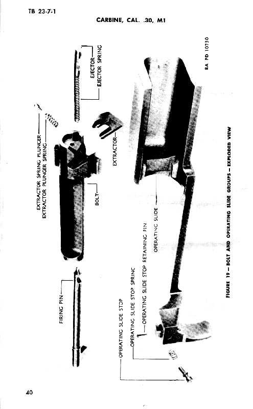
24. OPERATING SLIDE GROUP, DISASSEMBLY (Figure 19). -- The operating slide stop is the only rremovable part of the operating slide group. To remove operating slide stop, punch out retaining pin from right side. Be careful that stop and spring do not fly out when released. Lift stop and spring from well in operating slide.
25. OPERATING SLIDE GROUP, ASSEMBLY. -- Assemble operating slide stop spring to stop and insert into aperature in top of slide handle with head of stop facing out. Depress stop against force of spring and insert retaining pin from left side, and drive flush. Operate stop to test functioning. (Nose of stop should protrude only when stop is pressed against force of spring).
26. BOLT GROUP, DISASSEMBLY (Figure 19). -- The spindle of the extractor locks alll other components of the bolt group into the bolt. To disassemble, hold thumb over face of bolt to prevent the ejector and extractor spring plunger from flying out when released, and punch the extractor out from the underside of the bolt. Withdraw ejector and spring, extractor spring and plunger, and the firing pin from the bolt.
27. BOLT GROUP, ASSEMBLY. -- a. Insert firing
pin into well in rear of bolt so that tang on rear of firing pin fits into
aperature in rear end of bolt.
b. Assemble ejector spring
to ejector so that it is locked in groove in ejector shank, and insert ejector
assembly, spring first, into ejector well in lower front face of bolt.
c. Aline cut in firing pin with extractor spindle
hole in bolt. Compress ejector in well and aline cut with that in firing pin and
with extractor spindle hole. Insert hammer pin or similar pin into extractor
spindle hole, from bottom, far enough to hold ejector and firing pin in place.
d. Assemble extractor plunger spring to extractor
plunger and insert, spring first, into well in forward face of cam lug on right
side of bolt.
e. Start extractor spindle into
aperature hole in top of bolt and press extractor into aperature, camming
extractor plunger back into its well. Continue to press extractor home until it
pushes out the hammer (or holding) pin and seats in its aperature, flush with
top of bolt. Test spring functioning of extractor and ejector.
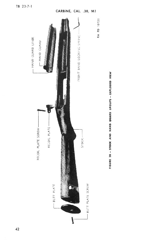
28. STOCK AND HAND GUARD GROUP, DISASSEMBLY (Figure 20). -- a. Front band locking spring. -- Inserrt small, straight punch in spring spindle hole in left side of forward end of stock and drive out front band locking spring (to the right) part way; spring may then be rotated and pulled from aperature.
b. Recoil plate. -- (1) Unscrew recoil plate screw
until clear of estutcheon threads (about ¾ inch), then withdraw from stock and
recoil plate.
(2) Tap lightly on rear top
face of recoil plate with a metal tool, and pull plate directly forward out of
seating aperature in stock. Do not pull up or down, because rear seating lug on
plate seats in a horizontal cut in the stock.
(3)
The estutcheon should not be removed from the stock except for replacement. To
remove, thread recoil plate screw all the way into estucheon from the underside
and pull estucheon out of stock. If withdrawl is difficult, insert small
straight punch from top of screw hole in stock and tap end of screw lightly to
loosen estucheon, or thread screw in from top, part way, and tap lightly, then
proceed as above.
c. Butt Plate. -- Unscrew butt
plate screw and remove from stock. Tap butt plate lightly with metal tool (to
loosen) and pull to rear off stock. If butt plate is tight, do not pull off as
stock is apt to be injured. Tap on edges lightly (all the way around) until
loose enough to pull from stock.
d. Hand guard. --
The liner of the hand guard assembly is rivited to the hand guard, and should
not be removed except in emergency or for salvage. To remove, file off riveted
head of rivets and punch out from the inside of hand guard.
29. STOCK AND HAND GUARD GROUP, ASSEMBLY. -- a.
Front band locking spring. -- insert spindle of spring into hole in right
forward end of stock, and drive to left. Seat spring fully in aperature in
stock.
b. Recoil plate. (1) insert recoil plate
into rear of reciever aperature in stock with bevel face up and tang to rear.
Recoil plate must be inserted from front to rear and held level during
insertion, so that seating lug and horizontal aperature mate. When in position,
tap lightly to seat evenly and flush with stock.
(2) If estucheon has been removed, insert small end first into aperature in
under face of stock grip. Tap in until seated level and flush with stock.
Replacew recoil plate screw through top of recoil plate and stock, thread into
estucheon and draw down snugly.
c. Butt Plate. --
Place butt plate on butt and tap lightly until solidly and evenly seated on
butt. Insert screw and turn down snugly. Do not force screw as threads in wood
of stock may strip.
d. Hand guard. -- If metal
liner has been removed for replacement, position liner in rear face of hand
guard so that it bears evenly on wood. Insert rivets from outside and rivet
against metal liner. This should not be attempted without proper tools, or hand
guard may be damaged. (Tubular rivets are used, which require a special riveter.
In emergency, a spotting punch may be used).